Making fancy visualizations of CAD construction sequences
Introduction
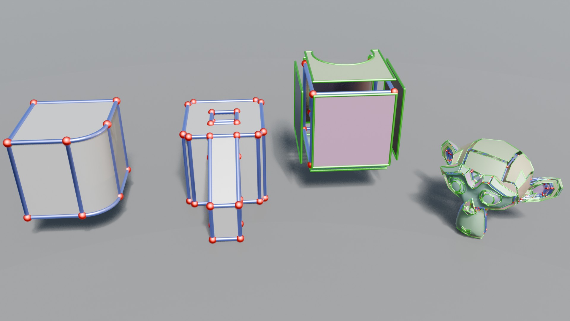
The lucky few who attended my thesis defense will no doubt have been blown away by my schematic animations illustrating the topology of computer-aided design representations. I actually created a couple of Blender modifiers to make this quite easy for myself (and hopefully, others in the future)—which can be applied to any mesh, with minimal manual intervention.
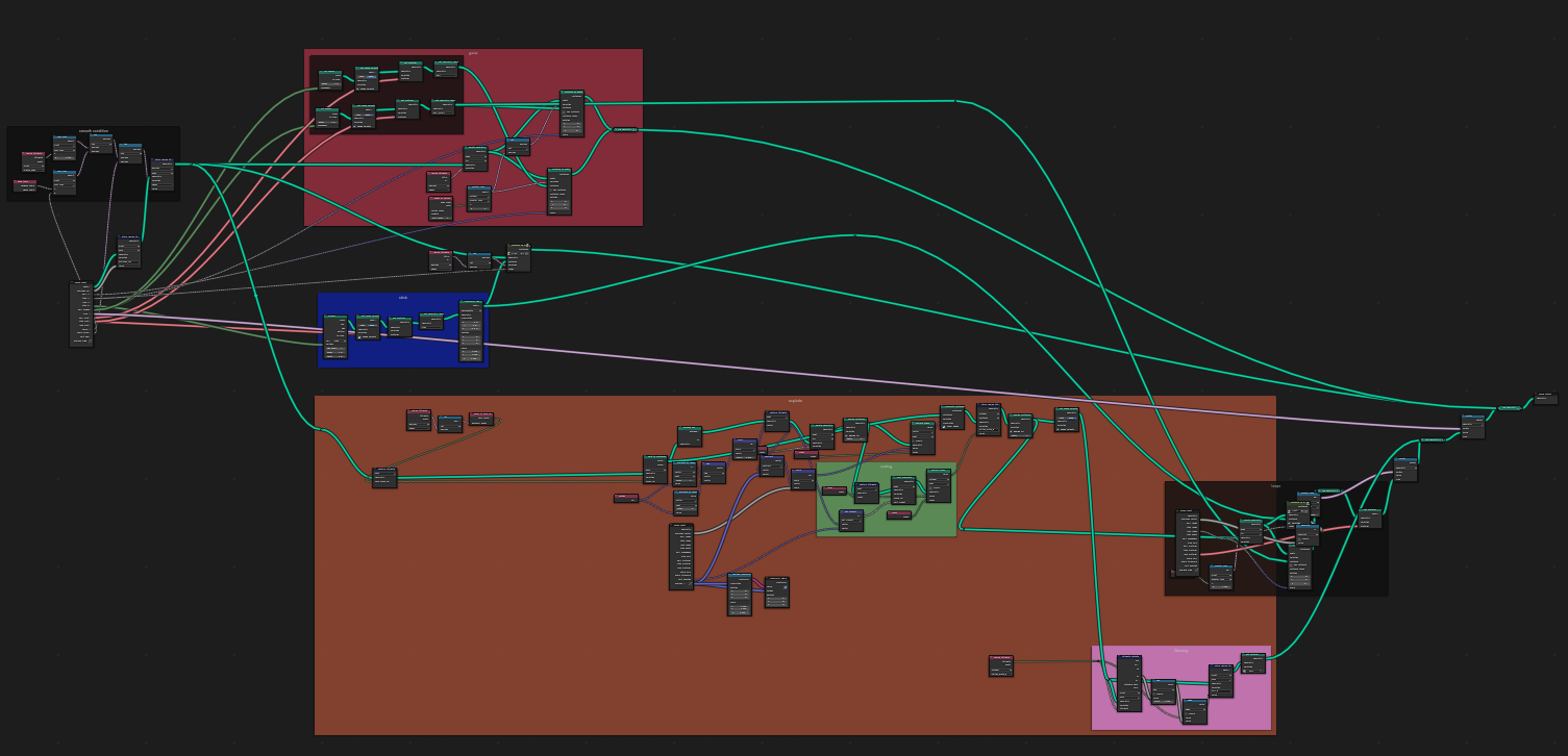
This was achieved using Geometry Nodes in Blender, a powerful tool for procedurally modifying and generating geometry.
B-Rep Visualization Tools
You can download the tool here (as a zipped .blend file).
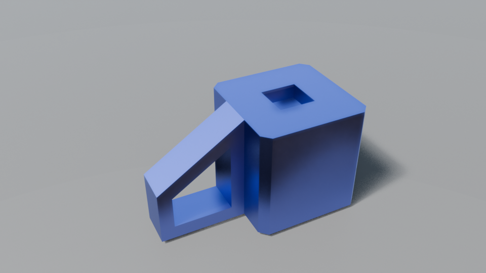
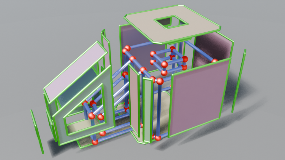
Simply extract the .blend file and place it in your Blender assets folder (whatever path is set in Blender Preferences -> File Paths -> Asset Libraries). You now have access to two modifiers: Creased Boolean and Wireframe. To understand what these do, let’s look at an example animation created using these tools:
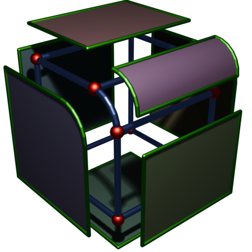
The mesh at each point in time is the result of performing various mesh boolean operations, placing wireframe edges and vertices wherever the meshes intersect. The exploded diagram is also procedural, computing on the fly which mesh faces are bounded by each closed loop in the wireframe and displacing them, as well as prettifying their boundary loops (green).
Creased Boolean
This is like the regular Boolean modifier in Blender, except it records extra information to be used by the Wireframe node to create our final exploded diagram. Namely, it records where the intersection edges of the meshes used in the boolean are, so that we can reliably render the boundaries of the two surfaces (This information is stored in as edge crease data, hence the name).
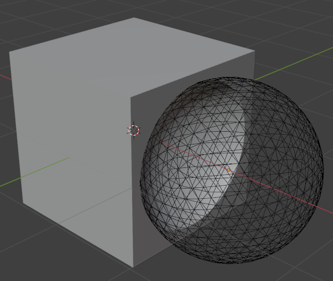
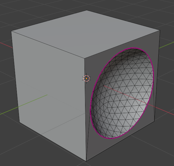
Wireframe
This is the modifier that does the heavy lifting. It should be placed after the Creased boolean modifier in the modifier stack.
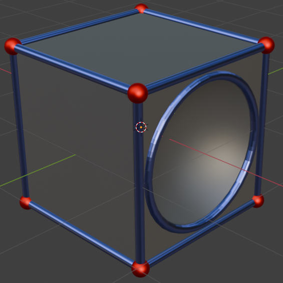
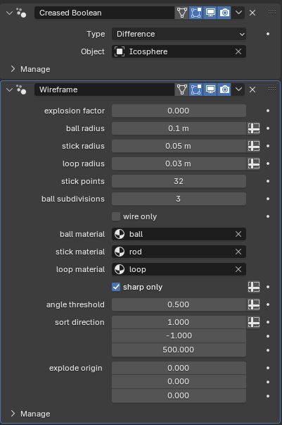
This modifier has many properties to control the state of the visualization, all of which can be animated as usual. Most pertinent is the explosion factor, which controls how “exploded” the faces are from the center. You can also move the center from which they emanate by dragging the transform gizmo which appears in the 3D viewport with the object selected, or changing the explode origin property in the modifier panel.
Another useful property is the angle threshold, which controls the angle (in radians) at which to consider a face part of the wireframe (the larger the value, the more edges will be “smoothed” out and rejected from the wireframe).
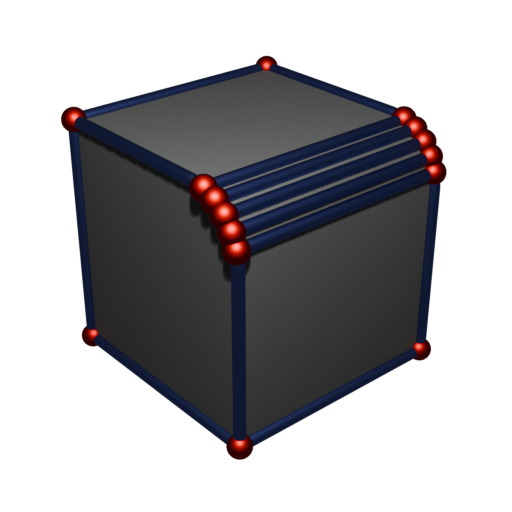
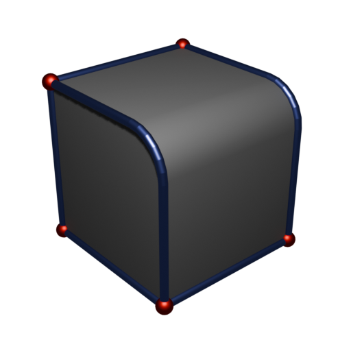
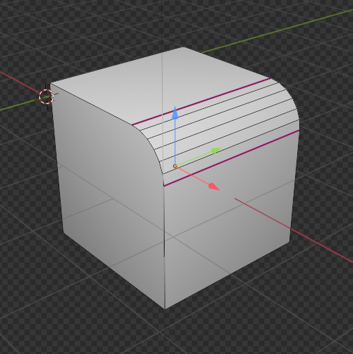
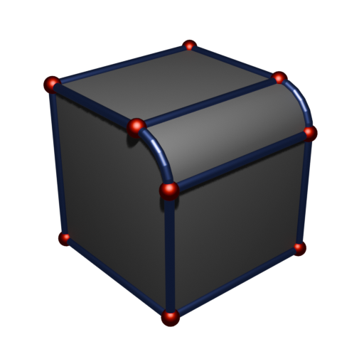
Remember how the Creased Boolean node stores extra boundary information in the edge crease data? Well, you can crease edges manually with shift+E, too, if you want those edges to be included in the wireframe. In this example, we probably want to visualize the boundary between the bevel surface and the planar surfaces, since in CAD software these would be represented by distinct parametric surfaces (cylinder and planes, respectively).
Closing remarks
Using these modifiers, you can create CAD-style visualizations in Blender, even if you don’t have a true CAD model, only a mesh (as often happens). What’s more, the properties exposed by these modifiers can be freely animated thanks to Blender’s flexibility, creating many creative effects beyond the realm of instructive visualization.